Manufacturers & Exporters of
Valves, Fittings & Boiler Mountings
Manufacturers & Exporters of
Valves, Fittings & Boiler Mountings
-
Features
Body Material Cum Standard
Cast Iron (IBR 86 to 93 Gr. A)
Product Description
Pilot Operated, Outlet Pressure Range available 5/45, 40/100, 90/125 Psig
Type of Seat
Renewable Seat
Trim
13% Cr. (SS 410) + Stellited Facing
End Details
Flanged Ends as per BS-10 Table-F Flat Face (Undrilled)
Test Pressure
Body: 300 Psig (Hyd.)
Max. Working Pressure
150 Psig (Steam)
Max. Working Temperature
220°C
Notes
Test Certificate in Form III-C as per IBR is furnished with every supply.
Suitability
Water
Steam
Gas
Oil
Air
-
Material Combination
S.No Description No. Material Specifications 1,2 Adjusting Screw, Locking Nut 1 Carbon Steel – 3 Spring Housing 1 S.G.I. EN 1563 Gr. GJS-400-15 4, 6 Spring Top Disc, Spring Bottom Disc 1 Stainless Steel AISI 410 5, 7 Pressure Adjusting Spring, Diaphragm 1 Stainless Steel AISI 304 8 Side Plug 1 Stainless Steel AISI 410 9, 10 Pilot Valve Body, Ball 1 Stainless Steel AISI 304 11 Pilot Valve Spring Retaining Check Nut 1 Stainless Steel AISI 304 12, 13 Main Valve Disc, Body Seat Ring 1 Stainless Steel AISI 410 + Stellite 14 Push Rod Guide Sleeve 1 Stainless Steel AISI 410 15 Main Valve Body 1 Cast Iron IBR 86 to 93 Gr.A 16 Main Diaphragm Disc 1 G.M. / S.S. IBR 282 (a) (iv) Gr. B / AISI 410 17, 18 Half Upper Cover, Half Lower Cover 1 Cast Iron IBR 86 to 93 Gr.A 19 Bolts & Nuts To Suit Carbon Steel – 20 Diaphragm 1 Stainless Steel AISI 304 21, 23 Gasket 1 C.A.F. IS 2712 22 Push Rod Lock Nut 1 Stainless Steel AISI 410 24 Strainer Screen 1 Stainless Steel AISI 304 25 Gasket 1 C.A.F. – 26 By Pass Assy. – – – 27, 28 Studs & Nuts To Suit Carbon Steel – -
Dimensional Data
Size (mm) FF H ØFD FT k n Ød 25 165 215 120.7 12.7 87.3 4 17.5 40 203 245 139.7 15.9 104.8 4 17.5 50 248 295 165.1 19.1 127 4 17.5

Features
Body Material Cum Standard
Cast Iron (IBR 86 to 93 Gr. A)
Product Description
Pilot Operated, Outlet Pressure Range available 5/45, 40/100, 90/125 Psig
Type of Seat
Renewable Seat
Trim
13% Cr. (SS 410) + Stellited Facing
End Details
Flanged Ends as per BS-10 Table-F Flat Face (Undrilled)
Test Pressure
Body: 300 Psig (Hyd.)
Max. Working Pressure
150 Psig (Steam)
Max. Working Temperature
220°C
Notes
Test Certificate in Form III-C as per IBR is furnished with every supply.
Suitability
Water
Steam
Gas
Oil
Air

Material Combination
S.No
Description
No.
Material
Specifications
1,2
Adjusting Screw, Locking Nut
1
Carbon Steel
–
3
Spring Housing
1
S.G.I.
EN 1563 Gr. GJS-400-15
4, 6
Spring Top Disc, Spring Bottom Disc
1
Stainless Steel
AISI 410
5, 7
Pressure Adjusting Spring, Diaphragm
1
Stainless Steel
AISI 304
8
Side Plug
1
Stainless Steel
AISI 410
9, 10
Pilot Valve Body, Ball
1
Stainless Steel
AISI 304
11
Pilot Valve Spring Retaining Check Nut
1
Stainless Steel
AISI 304
12, 13
Main Valve Disc, Body Seat Ring
1
Stainless Steel
AISI 410 + Stellite
14
Push Rod Guide Sleeve
1
Stainless Steel
AISI 410
15
Main Valve Body
1
Cast Iron
IBR 86 to 93 Gr.A
16
Main Diaphragm Disc
1
G.M. / S.S.
IBR 282 (a) (iv) Gr. B / AISI 410
17, 18
Half Upper Cover, Half Lower Cover
1
Cast Iron
IBR 86 to 93 Gr.A
19
Bolts & Nuts
To Suit
Carbon Steel
–
20
Diaphragm
1
Stainless Steel
AISI 304
21, 23
Gasket
1
C.A.F.
IS 2712
22
Push Rod Lock Nut
1
Stainless Steel
AISI 410
24
Strainer Screen
1
Stainless Steel
AISI 304
25
Gasket
1
C.A.F.
–
26
By Pass Assy.
–
–
–
27, 28
Studs & Nuts
To Suit
Carbon Steel
–
| S.No | Description | No. | Material | Specifications |
|---|---|---|---|---|
| 1,2 | Adjusting Screw, Locking Nut | 1 | Carbon Steel | – |
| 3 | Spring Housing | 1 | S.G.I. | EN 1563 Gr. GJS-400-15 |
| 4, 6 | Spring Top Disc, Spring Bottom Disc | 1 | Stainless Steel | AISI 410 |
| 5, 7 | Pressure Adjusting Spring, Diaphragm | 1 | Stainless Steel | AISI 304 |
| 8 | Side Plug | 1 | Stainless Steel | AISI 410 |
| 9, 10 | Pilot Valve Body, Ball | 1 | Stainless Steel | AISI 304 |
| 11 | Pilot Valve Spring Retaining Check Nut | 1 | Stainless Steel | AISI 304 |
| 12, 13 | Main Valve Disc, Body Seat Ring | 1 | Stainless Steel | AISI 410 + Stellite |
| 14 | Push Rod Guide Sleeve | 1 | Stainless Steel | AISI 410 |
| 15 | Main Valve Body | 1 | Cast Iron | IBR 86 to 93 Gr.A |
| 16 | Main Diaphragm Disc | 1 | G.M. / S.S. | IBR 282 (a) (iv) Gr. B / AISI 410 |
| 17, 18 | Half Upper Cover, Half Lower Cover | 1 | Cast Iron | IBR 86 to 93 Gr.A |
| 19 | Bolts & Nuts | To Suit | Carbon Steel | – |
| 20 | Diaphragm | 1 | Stainless Steel | AISI 304 |
| 21, 23 | Gasket | 1 | C.A.F. | IS 2712 |
| 22 | Push Rod Lock Nut | 1 | Stainless Steel | AISI 410 |
| 24 | Strainer Screen | 1 | Stainless Steel | AISI 304 |
| 25 | Gasket | 1 | C.A.F. | – |
| 26 | By Pass Assy. | – | – | – |
| 27, 28 | Studs & Nuts | To Suit | Carbon Steel | – |
Dimensional Data
Size (mm)
FF
H
ØFD
FT
k
n
Ød
25
165
215
120.7
12.7
87.3
4
17.5
40
203
245
139.7
15.9
104.8
4
17.5
50
248
295
165.1
19.1
127
4
17.5
| Size (mm) | FF | H | ØFD | FT | k | n | Ød |
|---|---|---|---|---|---|---|---|
| 25 | 165 | 215 | 120.7 | 12.7 | 87.3 | 4 | 17.5 |
| 40 | 203 | 245 | 139.7 | 15.9 | 104.8 | 4 | 17.5 |
| 50 | 248 | 295 | 165.1 | 19.1 | 127 | 4 | 17.5 |
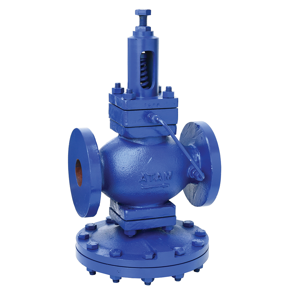
Selected Product
AV-263 Cast Iron Pilot Operated Pressure Reducing Valve, Flanged Ends

Enter Product Query
All Rights Reserved. Atam Valves Limited
